1.4.6 Resolving Feedback System Activity Diagram Errors

Activity-Diagram Feedback Points to a Difference in Process Logic

A UML activity diagram communicates:

  • where the process starts;
  • which actions occur;
  • where decisions occur;
  • which path applies to each decision result;
  • where the activity ends.

When the Feedback System reports an activity-diagram error, treat the message as evidence that the current model differs from the expected process.

Identify the Kind of Diagram Element Involved

Introductory activity-diagram issues can involve:

  • missing start node;
  • missing end node;
  • missing action;
  • incorrect action wording;
  • missing decision node;
  • incorrect branch direction;
  • incorrect decision path label;
  • missing connector;
  • an action connected in the wrong order;
  • an extra element that is not part of the required flow.

Start by identifying which category the feedback is describing.

Check the Process Order

Suppose the intended behavior is:
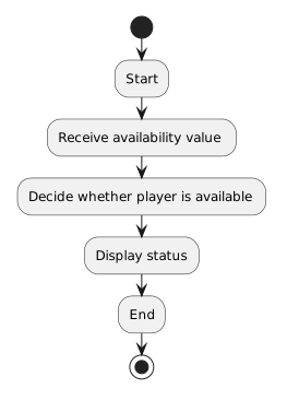
Activity diagram showing Start, then Receive availability value, then Decide whether player is available, then Display status, then End.
Start.
  • New
  • Changed
  • Removed

If your diagram places:

Display status

before the decision, the same nodes may all be present but the flow is still wrong.

Activity diagrams communicate sequence through their connectors.

Check Decision Paths Separately

Suppose the decision is:

Is player available?

The expected paths may be:

Activity diagram showing [true] Display "Available", then [false] Display "Unavailable".
TrueDisplayAvailable.
  • New
  • Changed
  • Removed

If those actions are reversed, the decision node exists but the model communicates the wrong logic.

Follow each branch from the decision to its outcome.

Confirm That Branch Labels Match the Condition

A branch labeled:

[true]

should correspond to the path followed when the decision condition evaluates to true.

A label should not be chosen merely because it makes the layout look balanced.

The path label has semantic meaning.

Check Start and End Boundaries

If the start node is missing, the reader may not know where to begin.

If a branch never reaches the intended end, the modeled activity may appear incomplete.

Trace every path:

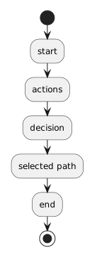
Activity diagram showing start, then actions, then decision, then selected path, then end.
Start.
  • New
  • Changed
  • Removed

Each valid path should describe a coherent process.

Do Not Convert the Diagram into C# Syntax

If feedback says the decision is wrong, do not fill the diagram with source-code statements unless the course's current UML notation explicitly requires that representation.

The activity diagram should express process logic at the appropriate model level.

Do Not Add Later Decision Structures

At the current Module 1.4 boundary, activity diagrams support simple decisions.

Do not repair a diagram by introducing:

  • later multi-branch conditionals;
  • compound Boolean operators;
  • return-value flows;
  • loop notation.

Those concepts belong later.

Use only the logic already taught.

Preserve Correct Parts of the Diagram

If the Feedback System identifies one incorrect branch:

  1. keep the correct actions;
  2. keep the correct start and end;
  3. revise the incorrect branch;
  4. save the editable Violet file;
  5. submit the current version;
  6. read the new feedback.

Focused changes make it easier to understand what correction mattered.

Compare the Diagram with the Requirement

Feedback tells you that a difference exists.

The requirement tells you what the model should mean.

For example, if the requirement says:

Then the activity path associated with false availability should lead to that action.

The requirement controls the logic.

Read the Diagram as Plain Language

After revising, explain the process:

If your diagram cannot support that explanation, the process is not yet clear.

The Goal Is a Correct Behavioral Model

The objective is not simply:

The objective is:

Feedback is evidence that helps you reach that model.