1.4.2 Activity Diagrams

Overview

A UML activity diagram answers:

Module 1.4 returns to activity diagrams because methods with parameters and Boolean decisions make process flow more important.

An activity diagram can represent:

  • where a process begins;
  • the actions that occur;
  • decisions that split the flow;
  • the paths followed after those decisions;
  • where the modeled process ends.

The diagram communicates behavior at a higher level than source code. Its job is to make the flow understandable.

Start at the Start Node

An activity diagram needs a clear place to begin reading.

The start node marks the entry point into the modeled process.

Conceptually:
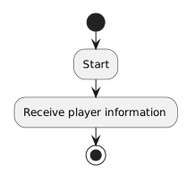
Activity diagram showing Start, then Receive player information.
Start.
  • New
  • Changed
  • Removed

The reader begins at the start node and follows the outgoing flow.

The start node does not perform work. It is not an action such as:

Create player

or:

Read parameter

The first action node after the start describes the first work that happens.

For example:
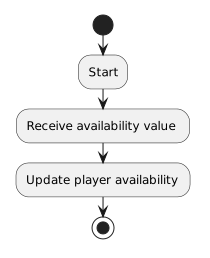
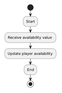
Activity diagram showing Start, then Receive availability value, then Update player availability.
Start.
  • New
  • Changed
  • Removed

At this introductory level, use one obvious starting point unless the current design explicitly requires something more complex.
The Start Node Belongs to the Scope of the Diagram

If an activity diagram models one method, the start node means:

It does not mean:

  • start the entire application;
  • create every object in the program;
  • launch Visual Studio.

The meaning of the start depends on what the diagram is modeling.

The arrow direction matters. Flow moves away from the start node toward the first meaningful action.

End at the End Node

An end node marks where the modeled activity is complete.

A simple activity might be:

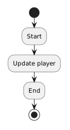
Activity diagram showing Start, then Update player, then End.
Start.
  • New
  • Changed
  • Removed

The end node defines the conclusion of the activity being modeled.

If the diagram represents one method, reaching the end means that the modeled method-level activity is finished. It does not necessarily mean:

  • the application closes;
  • the computer stops;
  • no other code can run.

Ask:

The answer should be the activity currently being modeled.

Start and End Define the Activity Boundary

Start and end nodes work together to make the scope of the process visible.

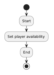
For example:

Activity diagram showing Start, then Set player availability, then End.
Start.
  • New
  • Changed
  • Removed

Everything between those nodes belongs to the activity being explained.

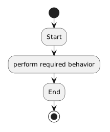
A method with one focused behavioral purpose can often be modeled with this same basic pattern:

Activity diagram showing Start, then perform required behavior, then End.
Start.
  • New
  • Changed
  • Removed

As the behavior becomes more complex, the activity can contain additional actions and decisions between those boundaries.

Read an Activity Diagram as a Flow

A simple process can be pictured as:

Activity diagram showing Start, then Receive availability value, then Update player availability, then End.
Start.
  • New
  • Changed
  • Removed

The arrows show the direction of flow.

Read from the start node, follow each arrow, read each action in order, follow any decision path that applies, and continue until the activity reaches its end.

If the flow cannot be followed clearly from start to end, revise the diagram structure.

Activity Diagrams Show Behavior, Not Source Syntax

An activity diagram might say:

Update player availability

The C# implementation might involve a method parameter and a field assignment.

The diagram does not need to reproduce every C# token.

Its job is to communicate the logic of the process.

Decisions Create Alternate Paths

A process does not always follow one straight sequence.

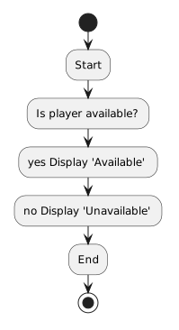
For example:

Activity diagram showing Start, then Is player available?, then yes Display "Available", then no Display "Unavailable", then End.
Start.
  • New
  • Changed
  • Removed

A decision causes the process to follow a path based on a Boolean result.

The Decision Nodes in Activity Diagrams page develops that branching behavior in more detail.

The Level of Detail Should Match the Purpose

A useful activity diagram shows enough detail for a reader to understand the behavior.

It should not become:

  • a line-by-line copy of source code;
  • a class diagram;
  • an object-state snapshot.

Use action wording that captures meaningful behavior at the current level of abstraction.

Activity Diagrams Can Help Before Coding

Before writing a method, an activity diagram can help you answer:

  • What happens first?
  • What actions occur?
  • Where is a decision needed?
  • What happens on each path?
  • Where is the modeled activity complete?

That makes the diagram a design tool rather than only documentation after the code exists.

Activity Diagrams Can Also Explain Existing Code

Suppose a method already exists.

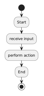
You can trace the method and model:

Activity diagram showing Start, then receive input, then perform action, then End.
Start.
  • New
  • Changed
  • Removed

If the method includes a decision, the diagram can show the alternate flow without copying the source line by line.

This can make the logic easier to understand than reading source syntax alone.

Keep Activity Diagrams Distinct from Sequence Diagrams

An activity diagram focuses on:

A sequence diagram focuses on:

Both can describe behavior.

They emphasize different aspects of that behavior.

Module 1.4 Adds Parameter-Aware Thinking

Methods now receive information from callers.

An activity diagram can show the behavior that uses that information.

For example:

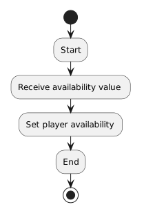
Activity diagram showing Start, then Receive availability value, then Set player availability, then End.
Start.
  • New
  • Changed
  • Removed

The parameter belongs to the method design.

The activity diagram shows what the method does with the incoming information.