An Activity Diagram Shows a Process
A UML activity diagram represents what happens and how the process flows from one action to another.
Before adding decisions, begin with the three basic parts of a straight process:
- a start;
- one or more actions;
- an end.
For a simple soccer process:
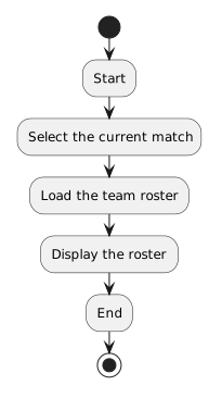 Start.
The diagram gives the reader a clear path to follow.
The Start Node Shows Where the Flow Begins
A UML activity diagram uses a start node to show where the activity begins.
There should be a clear point where the reader can enter the process.
In plain language:
The start node does not describe an action by itself.
It marks the beginning of the flow.
Action Nodes Describe Work
An action node represents something that happens.
Examples in a soccer system might include:
- Select current match
- Load team roster
- Display available players
- Record player availability
Action labels should describe meaningful work.
A vague label such as:
does not help the reader understand the process.
A stronger label tells what action occurs.
Arrows Show the Direction of Flow
Connections between nodes show which action follows another.
For example:
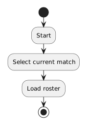 Start.
The arrows communicate sequence.
They tell the reader:
A diagram with correct actions but incorrect arrows communicates the wrong process.
The End Node Shows Where the Activity Finishes
An end node shows where the modeled activity is complete.
For a small process:
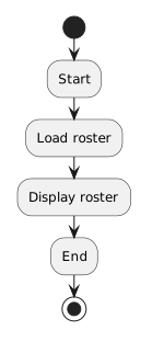 Start.
The end tells the reader that no additional action is part of this modeled path.
The real software may continue doing other things outside the scope of the diagram.
The end node marks the end of this activity model, not necessarily the end of the entire application.
Keep Action Labels Focused
An action node should usually describe one meaningful step.
Compare:
with:
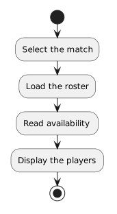 SelectTheMatch.
The second version makes the flow easier to follow because each action has a focused role.
Model the Needed Scope
An activity diagram is still an abstraction.
If the purpose is to show how the program displays a roster, the diagram does not need to include every event in the soccer club.
It may not need to show:
- how the player registered months ago;
- how the field was reserved;
- who washed the uniforms;
- or how the coach arrived at the field.
Include the actions needed to communicate the process being modeled.
Straight Flow Comes Before Branching
A basic activity diagram can represent one path:
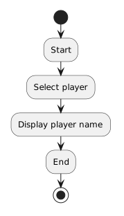 Start.
That is enough to show sequence.
Soon, you will add a point where the path can change based on a Boolean condition.
Before doing that, make sure the straight portions of the process are clear.
A decision is easier to understand when the actions before and after it already make sense.
Read the Diagram From Beginning to End
When reading an activity diagram:
- Find the start node.
- Follow the outgoing arrow.
- Read each action in order.
- Follow every connection exactly as drawn.
- Stop when the path reaches the end node.
Do not jump around the page based on which box looks closest.
The connectors define the flow.
The Main Structure
For a simple process, keep this mental model:
Start → Action → Action → End
The start establishes entry.
Actions describe the work.
Arrows establish order.
The end establishes completion.
The next activity adds a new kind of node that allows the flow to choose between different paths.