0.3.5 Flowcharts and Activity Diagrams

A Process Can Be Easier to Understand When You Can See the Flow

Written instructions show a process as text.

A visual flow diagram shows the same idea spatially.

Consider this simple soccer process:

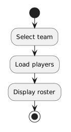
  1. Select the current match.
  2. Load the team roster.
  3. Display the player list.

As a visual flow:

Plain text
Select current match
        ↓
Load team roster
        ↓
Display player list

The arrows make the order immediately visible.

The diagram answers:

What happens next?

That makes flow diagrams useful when a process has enough steps that the sequence becomes difficult to hold in your head.
Flowcharts Are General-Purpose Process Diagrams

A flowchart is a common way to show the flow of actions through a process.

Flowcharts are used in many fields, not only programming.

A flowchart can help describe:

Different organizations may use somewhat different conventions.

The main idea is that shapes and arrows communicate actions and the paths between them.

UML Activity Diagrams Are a Standardized Modeling Form

A UML activity diagram is a UML diagram used to represent behavior or process flow.

Like a flowchart, it can show actions and the paths between them.

UML activity diagrams are useful in software work because they provide a standardized modeling language that can connect process reasoning to software requirements and behavior.

In this course, activity diagrams will become one of the ways you model:

Start With a Straight Path

Before working with decisions, look at a simple linear process.

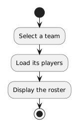
A soccer application may need to:

Plain text
Select a team
      ↓
Load its players
      ↓
Display the roster

There is one path.

Each action leads to the next action.

This is the visual equivalent of a basic sequence.

You do not need branching to benefit from the diagram.

Even a straight flow can make order and dependencies easier to see.

The Diagram Should Match the Process

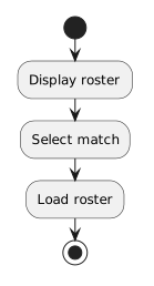
Suppose the written process says:

  1. Select the match.
  2. Load the roster.
  3. Display the roster.

But the diagram shows:

Plain text
Display roster
      ↓
Select match
      ↓
Load roster

The diagram is not merely arranged differently.

It communicates a different process.

A visual model is still a technical representation.

Its order and connections need to match the intended behavior.

Actions Should Describe Meaningful Work

A diagram is easier to understand when each action says what happens.

Compare:

Do it

with:

Load the team roster

The second label communicates meaningful behavior.

Avoid making an activity diagram into a picture of vague verbs.

Each action should contribute to the process being modeled.

Activity Diagrams and Object Diagrams Answer Different Questions

You have already used UML object diagrams.

An object diagram helps answer:

What specific objects and relationships exist in this snapshot?

An activity diagram helps answer:

What happens, and in what flow?

Consider a soccer application.

An object diagram might show:

An activity diagram might show:

Plain text
Select team
      ↓
Load players
      ↓
Display roster

One diagram focuses on state and structure.

The other focuses on process and flow.

Both can describe the same system from different perspectives.

Flow Diagrams Help Reveal Missing Steps

Suppose your process is written as:

  1. Display the roster.
  2. End.

A visual flow may make you notice that the program never identified which team or roster to use.

The missing information becomes easier to see when you ask what each action receives from the action before it.

That is one reason diagrams are useful before or while writing code.

They can expose gaps in the reasoning.

The Visual Flow Can Prepare You to Read Code

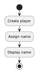
A straight process:

Plain text
Create player
      ↓
Assign name
      ↓
Display name

can correspond to a straight sequence of source statements.

The diagram does not contain C# syntax.

The C# does not look like the diagram.

But both can represent the same order of behavior.

Later, you will make this connection more directly.

Decisions Come Next

Real programs do not always follow one straight path.

A soccer process may eventually need to ask something like:

Is the player available?

Different answers can lead to different actions.

That introduces a decision and multiple paths.

The next batch develops the Boolean and UML notation needed to represent those choices precisely.

For now, the important foundation is simpler:

A visual flow diagram represents actions and the order or path connecting them.

Choose the Representation That Answers the Question

Use an object-oriented snapshot when the main question is:

What objects and values exist?

Use a process-flow representation when the main question is:

What happens next?

Learning to choose the representation that matches the question is part of modeling well.