1.5.6 Representing if and if/else Statements in Activity Diagrams

Activity Diagrams Can Model Conditional Program Flow

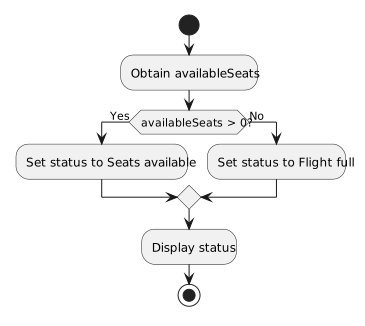
A C# decision can be represented visually with a UML activity diagram.

The purpose is not to copy C# punctuation into boxes.

The purpose is to show:

  • where the decision occurs;
  • what condition is being considered;
  • which path applies when the result is true;
  • which path applies when the result is false;
  • where the paths continue afterward.
Model a Simple if Statement

Consider:

if (player1.isAvailable)
{
    System.Console.WriteLine("Player is available.");
}

A conceptual activity flow is:

Start
  ↓
Is player available?
     ◇
   /   \
[true] [false]
  |       |
Display   |
available |
  \       /
   \     /
    ↓   ↓
  Continue
     ↓
    End

The true path contains the action controlled by the if.

The false path skips that action.

Both paths can continue with the rest of the activity.

The False Path of a Simple if May Contain No Special Action

In C#:

if (player1.isAvailable)
{
    System.Console.WriteLine("Player is available.");
}

System.Console.WriteLine("Roster reviewed.");

when availability is false, the program simply skips the controlled block.

The activity diagram should communicate that the false path bypasses the conditional action and rejoins the continuing flow.

Do not invent an extra false-path action when the source does not have one.

Model an if/else Statement as Two Explicit Paths

Consider:

if (player1.isAvailable)
{
    System.Console.WriteLine("Player is available.");
}
else
{
    System.Console.WriteLine("Player is unavailable.");
}

A conceptual activity diagram is:

     Is player available?
              ◇
            /   \
      [true]     [false]
        |           |
        v           v
Display available   Display unavailable
        |           |
        +-----+-----+
              |
              v
            End

The decision has two outcomes.

Each outcome has its own action.

The Decision Node Represents the Boolean Question

The decision node should communicate the question that controls the branch.

For example:

Is player available?

This corresponds to the Boolean expression:

player1.isAvailable

The diagram does not need to reproduce:

if (player1.isAvailable)

as C# syntax.

The UML should communicate the behavior.

Label the Paths According to the Condition Result

For an introductory Boolean decision, useful labels are:

[true]
[false]

The label tells the reader which condition result follows that path.

For:

Is player available?

the true path means:

The false path means:

Equality Comparisons Can Be Expressed as Questions

Suppose the C# is:

if (player1.position == "Goalkeeper")
{
    System.Console.WriteLine("Goalkeeper instructions.");
}
else
{
    System.Console.WriteLine("Field-player instructions.");
}

The activity decision can be phrased:

Is the player's position "Goalkeeper"?

Then the branches can be:

[true]  → Display goalkeeper instructions
[false] → Display field-player instructions

The diagram captures the meaning of the comparison rather than its exact source syntax.

Relational Comparisons Work the Same Way

C#:

if (team1.score >= 3)
{
    System.Console.WriteLine("Three or more goals.");
}
else
{
    System.Console.WriteLine("Fewer than three goals.");
}

Activity decision:

Is the score at least 3?

Branches:

[true]  → Display three-or-more message
[false] → Display fewer-than-three message

The diagram and the C# ask the same logical question.

Null Checks Can Also Be Modeled

C#:

if (player1.team == null)
{
    System.Console.WriteLine("No team assigned.");
}
else
{
    System.Console.WriteLine("Team assigned.");
}

Activity decision:

Is the team reference null?

Branches:

[true]  → Display no-team message
[false] → Display team-assigned message

Again, the diagram communicates the runtime decision.

Rejoin the Flow When Both Paths Continue

After an if/else finishes, later statements may run regardless of which branch was selected.

Conceptually:

       decision
      /        \
true path    false path
      \        /
       \      /
       continue

The visual should make that continuation clear.

The two branches do not represent separate programs.

They are alternate paths through one activity.

Do Not Show Both Branches as Running

For one evaluation of a basic if/else, the program does not execute both branch actions.

The decision selects one path.

If a diagram visually suggests that both paths run sequentially, it misrepresents the C# behavior.

Keep the Diagram at the Current Level

At this point, model:

  • one if;
  • or one if/else.

Do not add:

  • nested decisions;
  • loop structures;
  • several chained else if decisions.

The next Learning Activities expand the model to multiple decisions.

Read the Diagram Back Against the Code

For every branch, ask:

  1. What condition is being tested?
  2. Which path represents true?
  3. Which path represents false?
  4. Which C# block corresponds to each path?
  5. Where does the program continue afterward?

If the answers match the source logic, the activity diagram and C# are describing the same decision.