A UML activity diagram gives you a visual representation of process flow.
C# source gives the computer executable instructions.
The two representations do not look alike, but they can describe the same sequence and decision.
Consider this simple soccer activity:
Start
↓
Read player availability
↓
Decision: available?
├─ [yes] → Display "Available"
└─ [no] → Continue
↓
End
To translate the diagram, work one part at a time rather than trying to convert the whole picture at once.
The activity diagram's start node tells you where the modeled flow begins.
Its end node tells you where that modeled flow finishes.
C# does not require you to write a special “start node” statement or “end node” statement for this simple mapping.
Instead, the code lives inside the appropriate supplied method or event handler.
The surrounding course project determines that location.
Your job is to translate the actions and decisions inside that activity.
Suppose the diagram contains:
Display player name
A corresponding C# statement in a supplied application might cause a user-interface element to display a value.
The exact statement depends on the project.
The important mapping is:
Activity action → C# statement or small group of statements that performs that action
Do not invent a new control, class, or project structure when the supplied project already defines how the action should occur.
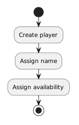
Consider:
Create player
↓
Assign name
↓
Assign availability
A matching introductory C# sequence could look like:
Player player1 = new Player();
player1.name = "Jordan";
player1.isAvailable = true;
The order matters.
The diagram's arrows show the sequence.
The C# statements appear in the corresponding execution order.
This is the same sequence reasoning you have already practiced.
A UML decision node asks a condition and sends execution down the matching path.
Conceptually:
Is player available?
├─ [yes] → Display "Available"
└─ [no] → Continue
In C#, decisions are represented with conditional statements.
At this point, you only need the connection:
Decision node → condition that selects a C# path
The next Learning Activities focus directly on reading simple if and if/else syntax.
For now, do not try to memorize conditional syntax from the diagram translation alone.
Focus on preserving the meaning of the paths.
Choose one Boolean state.
Suppose:
isAvailable = true
Follow the activity diagram from start to end.
Write the actions in the order that occur on that path.
Then repeat with:
isAvailable = false
If the paths differ, the C# implementation also needs a way to preserve that difference.
This path-by-path reasoning is more reliable than translating shapes mechanically.
A box being physically above another box does not automatically define execution order.
The connectors do.
Likewise, two boxes appearing beside each other does not automatically mean they are alternatives.
The decision and outgoing paths define the alternatives.
When translating:
Then connect those meanings to the source structure.
Suppose the diagram's decision depends on:
Is the player available?
The program needs information that represents that same condition.
Earlier, you used:
isAvailable
as a Boolean field.
The diagram and source should agree about the meaning of the condition.
A mismatch such as:
would represent different logic even if both artifacts look technically valid.
Once a supplied C# implementation is available, you can compare the model with runtime evidence.
A useful process is:
That connects:
UML model → C# source → runtime behavior
The goal is not to make each UML shape correspond to exactly one line of code.
The goal is to preserve the modeled behavior.
One action may require more than one C# statement.
Some project setup code may exist that does not appear in the activity diagram.
The question is:
Does the relevant C# flow perform the actions and decisions represented by the diagram?
That is the connection you will use when you begin reading simple conditional statements directly.