1.1.23 How to Translate a UML Object Diagram to C# Code

Begin with the Object Diagram, Not with C# Syntax

A UML object diagram describes a particular snapshot of a system. Before writing C#, read the model in a consistent order:

  1. Identify each object instance.
  2. Identify the type of each object.
  3. Read the field values shown inside each object.
  4. Follow the relationships between objects.

Consider this small soccer model:
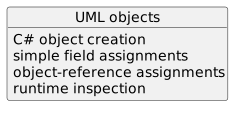
Object diagram showing UML objects, then C# object creation, then simple field assignments, then object-reference assignments, then runtime inspection.
UMLObjects.
  • New
  • Changed
  • Removed

This order helps prevent a common error: trying to use a related object before it has been created or connected.
Read the Finished C# Back Against the UML

A small translation can look like:

Player player1 = new Player();
Team team1 = new Team();

player1.name = "Jordan";
player1.jerseyNumber = 7;
team1.name = "Wildcats";

player1.team = team1;

Now read the code as a model:

  • one Player object exists;
  • one Team object exists;
  • the Player has the required values;
  • the Team has the required value;
  • the Player refers to the Team.

If that story differs from the UML, the translation is not finished.

The Debugger Provides Runtime Evidence

After the statements execute, inspect the objects in Visual Studio.

You should be able to follow:

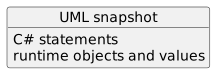
Object diagram showing UML snapshot, then C# statements, then runtime objects and values.
UMLSnapshot.
  • New
  • Changed
  • Removed

The diagram describes the intended state. The source contains the instructions. The debugger shows the state that actually exists.

Preserve the Model Exactly

Do not add extra objects, values, or relationships just because the C# class permits them.

For each important statement, ask:

That traceability is the foundation for moving between design and code.