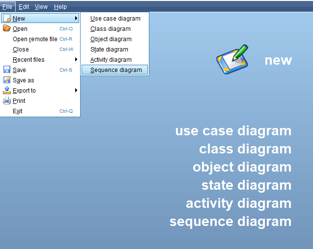
To create a new sequence diagram, open Violet and select File --> New --> Sequence Diagram.
To begin creating a sequence diagram, the first thing you are going to do is create an 'object lifeline' node. To do this, select the 'Object lifeline' tool in the 'Diagram tools' toolbar and click into the workspace.
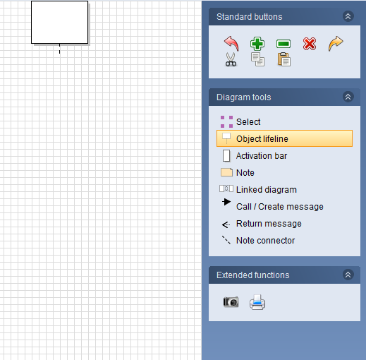
Object lifelines signify an object becoming active. More specifically, it means that an object is going to either make a call or be called on.
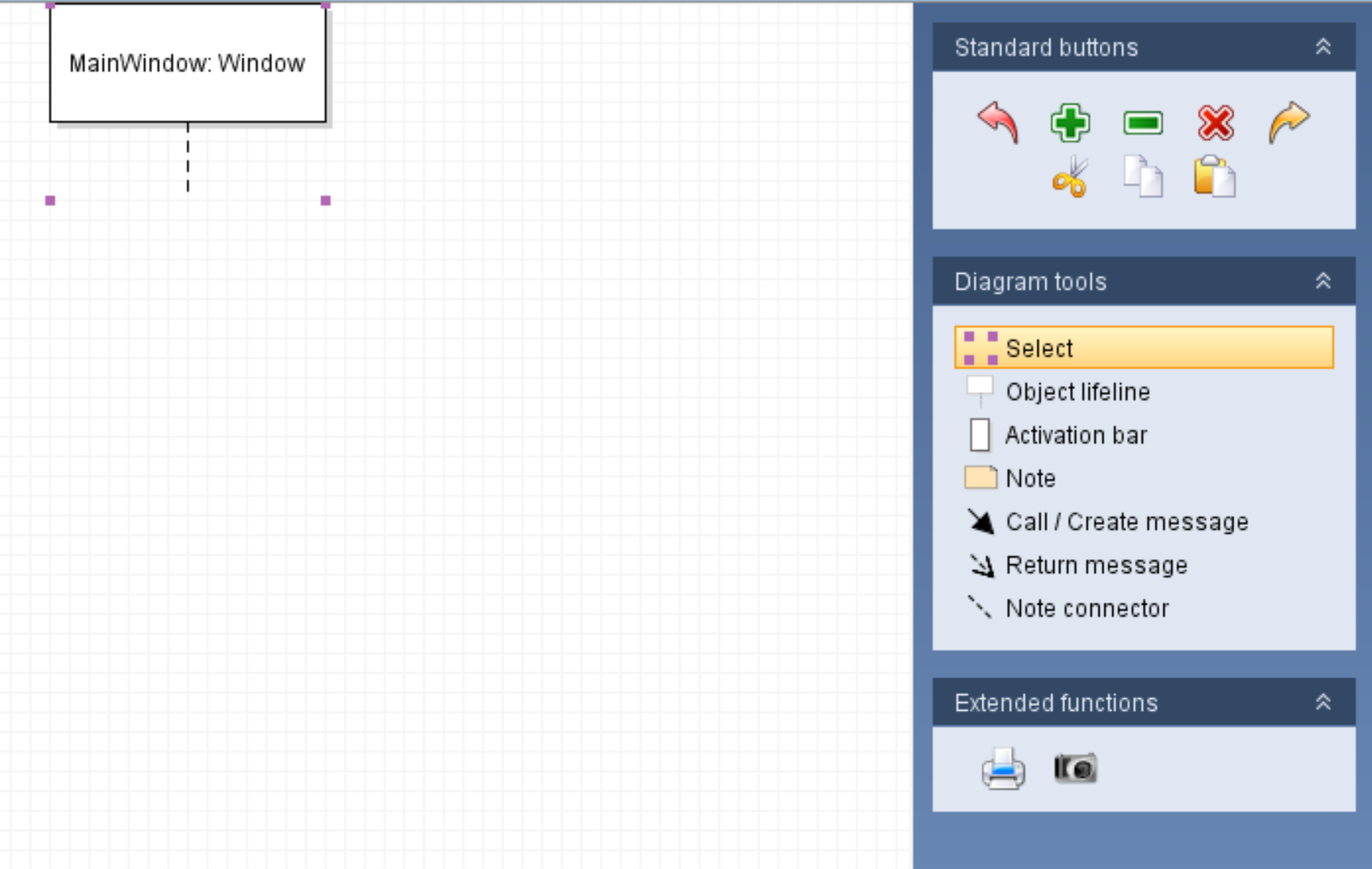
Object lifelines are labeled with an Object to Class notation and will always be at the top of the diagram.
To edit this object lifeline node, ensure the 'Select' tool is highlighted from the Diagram tools and double click the node.
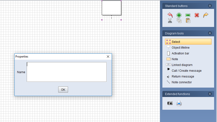
In the properties window, enter the label for the object lifeline. For this first one we will only put MainWindow because that is where our calls start from.
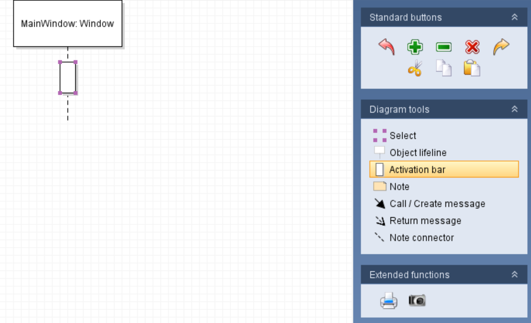
Next we need to add an activation bar to the object lifeline. An activation bar represents the method body that is active at any given time.
In the MainWindow the activation bars will represent event handlers.
To create an activation bar, ensure the 'Activation bar' tool is highlighted and click the dotted line below the object lifeline node.
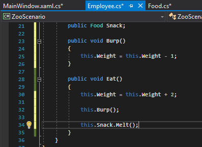
The activation bar, then, represents the method in the MainWindow shown below.
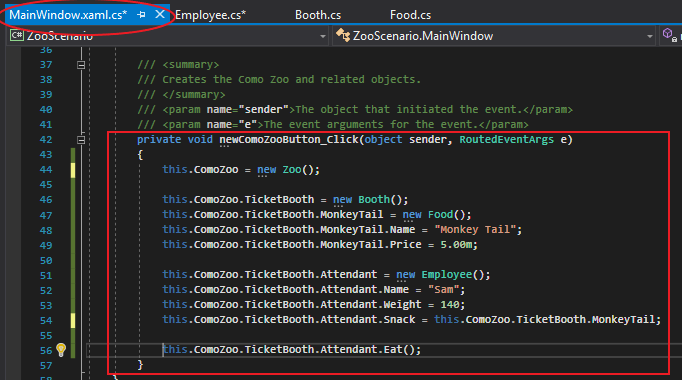
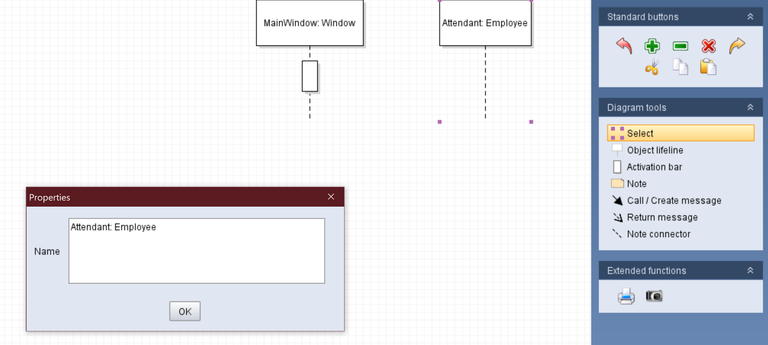
Within that method, we can see that there is a call to the Attendant's Eat method so we need to create another object lifeline node. This time, however, we will be following proper labeling conventions by using the Object: Class notation; Attendant being the Object and Employee being the class.
To create the call to the Attendant's Eat method, select the 'Call/Create message' tool, click and hold down on the MainWindow's activation bar, drag to the Attendant's lifeline and release. An arrow should appear and an activation bar on the Attendant's lifeline should appear.
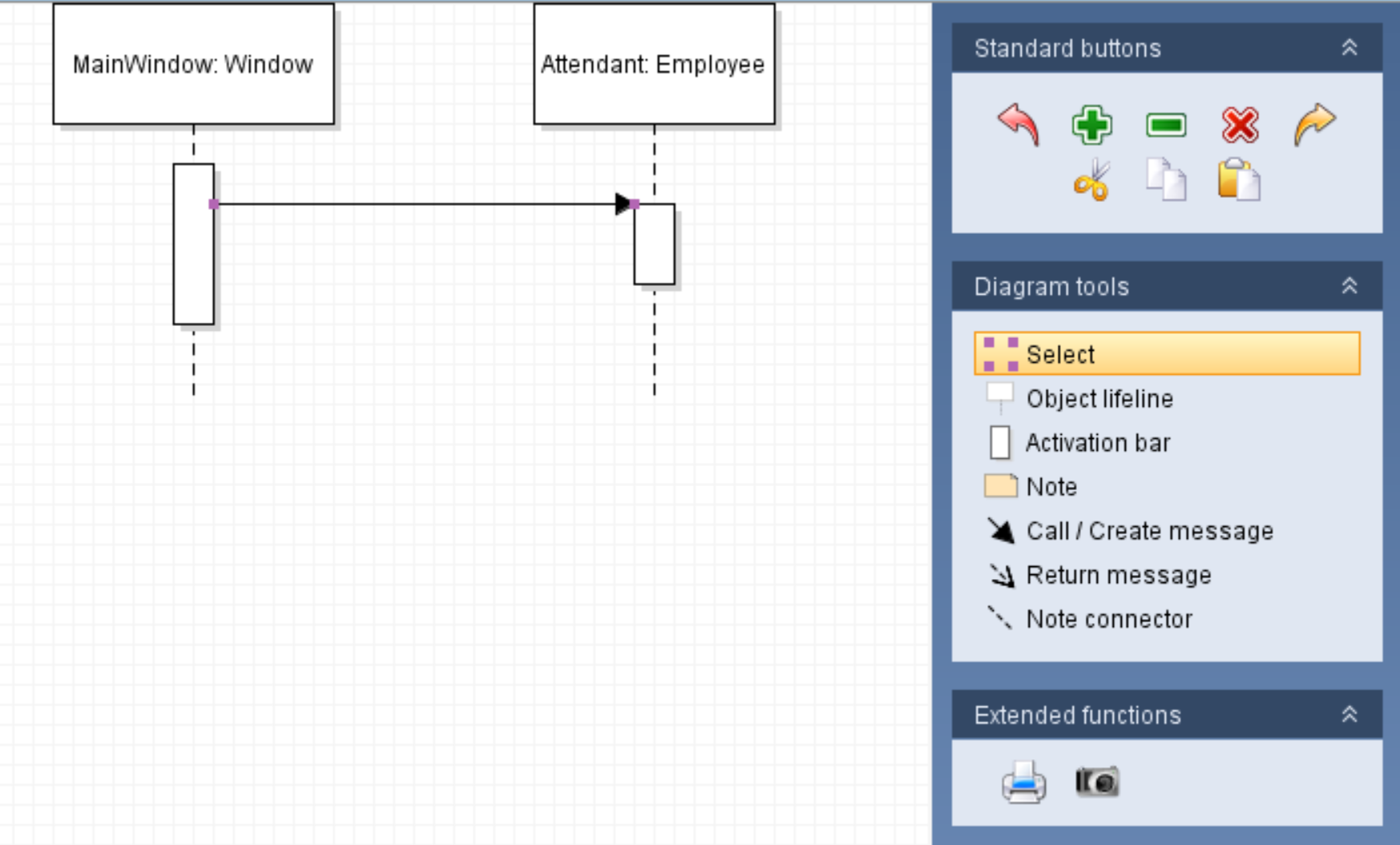
Then, ensure the 'Select' tool is highlighted and double click the arrow to bring up the properties window. In the middle label, type in the method being called and press okay. In this case it's the Eat method.
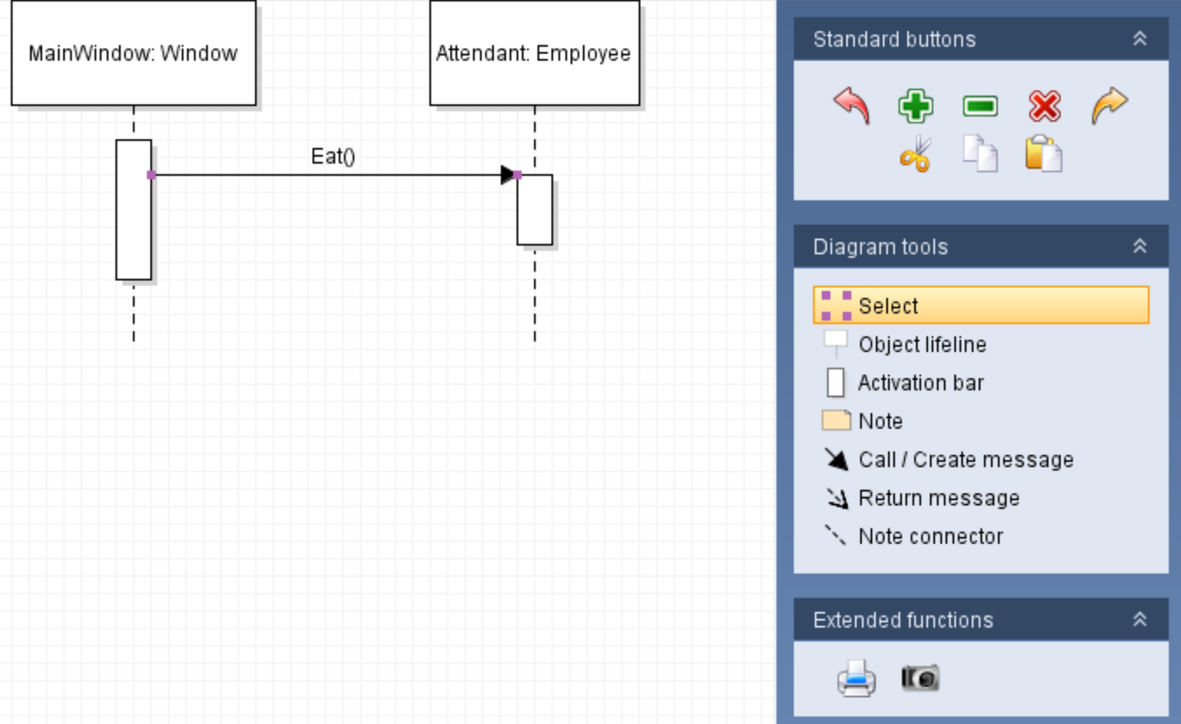
The diagram above can now be read as: "The Eat method is being called from the MainWindow on the Attendant object."
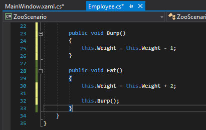
In the Eat method in the Employee class, then, there is a call to Burp in the same class.
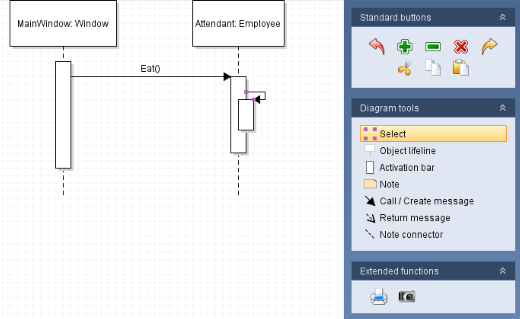
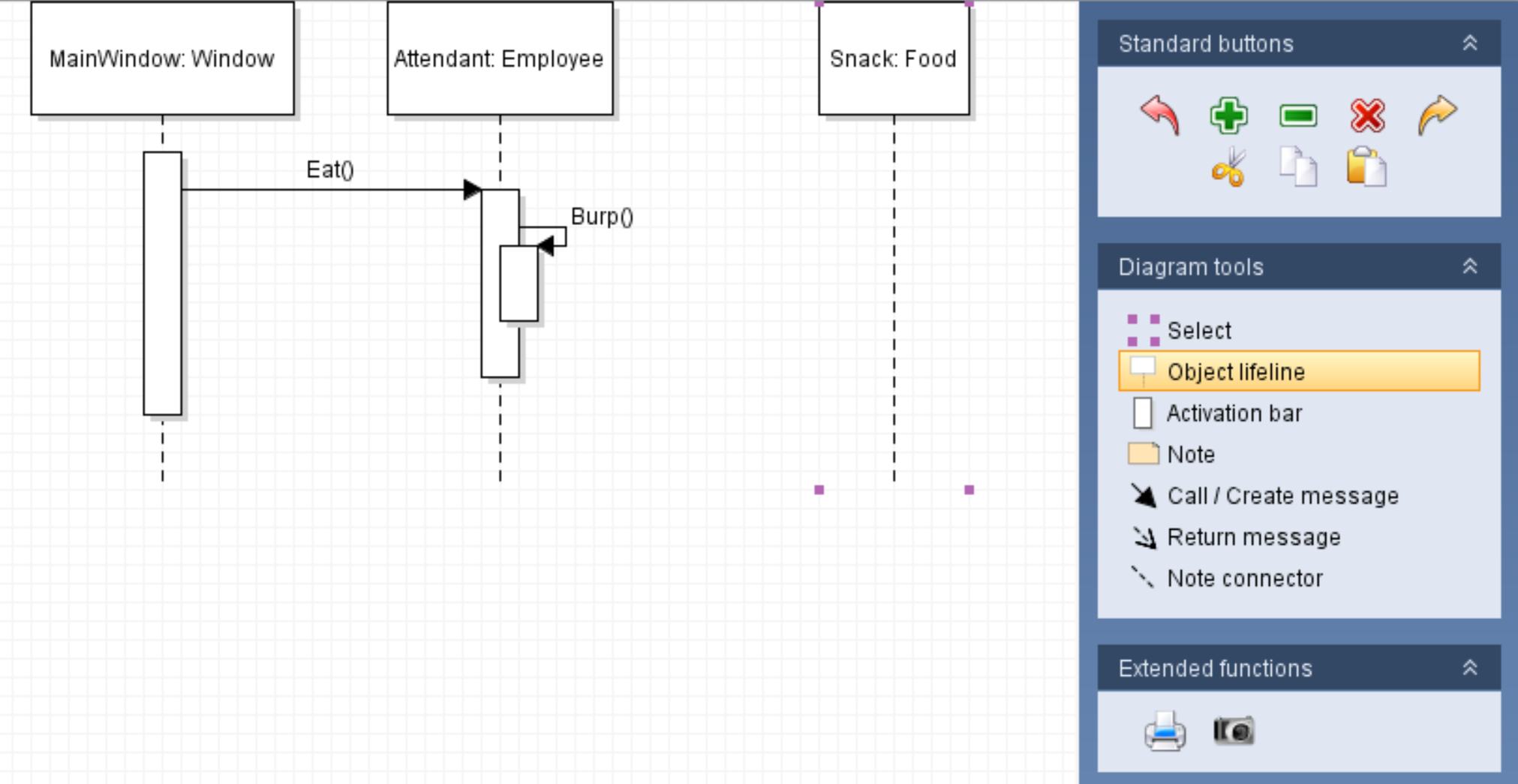
Calls within the same class do not require new object lifeline nodes. Instead, they are represented by a circular call in the activation bar they are being called from. To do this, ensure the 'Call/Create message' tool is selected, click and hold down on the Attendant's Eat method activation bar, drag down and then counter-clockwise until you are back on the activation bar and release. This can be tricky and may take a few tries.
Then, ensure that the 'Select' tool is highlighted and double-click on the connecting line to bring up the properties window. In the properties window, type the method being called. In this case it's Burp.
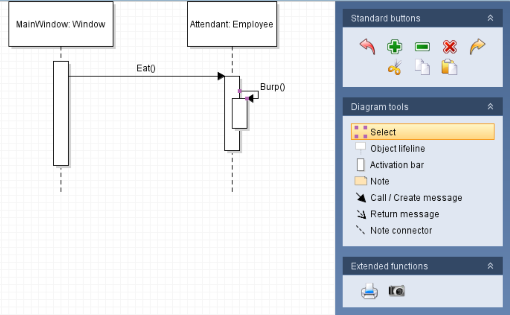
The diagram above can now be read as: "The Eat method is being called from the MainWindow on the Attendant object then the Burp method is being called from the Eat method."
So let's say that after burping, the snack Sam's eating begins to melt.
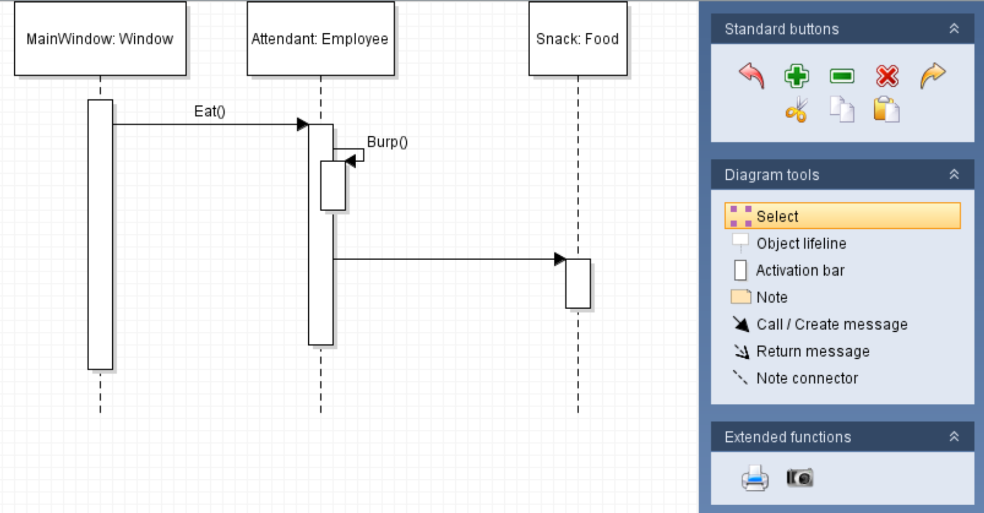
This is now a call to a completely different object so we will have to create a new object lifeline node.
However, note that the call to Melt is inside the Eat method, not the MainWindow or the Burp method and it's also after the call to Burp. To connect the two then, you will need to ensure the 'Call/Create message' tool is selected, click and hold on the Eat method's activation bar below the call to Burp, drag over to the Snack's lifeline and release.
Then, double click the call and type in the name of the call.
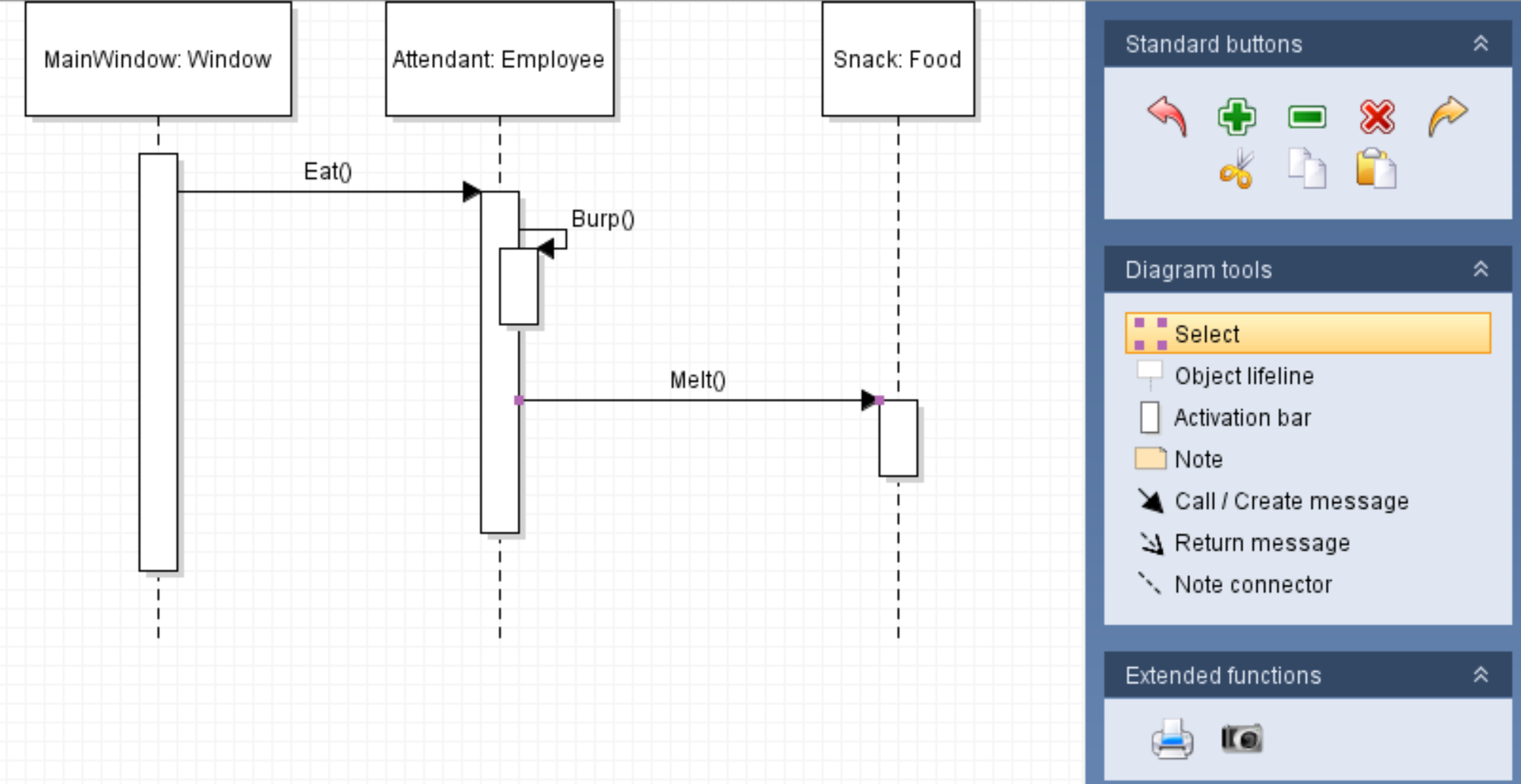
The diagram above can now be read as: "The Eat method is being called from the MainWindow on the Attendant object then the Burp method is being called from the Eat method and then the Melt method is called from the Eat method on the Snack object."
Remember that sequence diagrams are always read from top to bottom.