0.5.9 Modeling a Web Request With a UML Activity Diagram

Begin With the Interaction You Want to Explain

A web request can involve many technical details.

Your first model should stay focused on the responsibilities already introduced:

The purpose of the UML activity diagram is to make that flow and responsibility visible.

Use Browser and Server Partitions

Create two activity partitions:
Plain text
Browser / Client
Server

The Browser lane contains browser actions.

The Server lane contains server actions.

The flow will cross between them when the request and response move between systems.

Start in the Browser Lane

The user is interacting with the browser, so the modeled web flow can begin in the Browser lane.

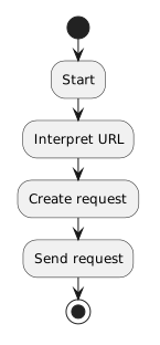
An introductory sequence might begin:

Plain text
Start
  ↓
Interpret URL
  ↓
Create request
  ↓
Send request

The next step occurs on the server.

Cross to the Server

After the browser sends the request, the activity flow crosses into the Server partition.

The server-side sequence can be modeled as:
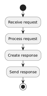
Plain text
Receive request
      ↓
Process request
      ↓
Create response
      ↓
Send response

You do not need to model the server's internal implementation in detail.

The current purpose is to show the server's responsibility in the request/response exchange.

Cross Back to the Browser

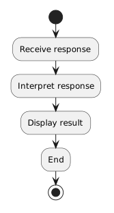
After the server sends the response, the flow returns to the Browser lane.

The browser can then:
Plain text
Receive response
      ↓
Interpret response
      ↓
Display result
      ↓
End

This produces a complete round trip.

A Complete Conceptual Flow

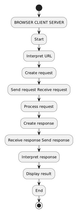
The model can be read as:

Plain text
BROWSER / CLIENT                SERVER

Start
  ↓
Interpret URL
  ↓
Create request
  ↓
Send request  ----------------> Receive request
                                ↓
                                Process request
                                ↓
                                Create response
                                ↓
Receive response <------------ Send response
  ↓
Interpret response
  ↓
Display result
  ↓
End

The exact rendered UML will use activity-diagram notation and partitions rather than plain text.

The meaning should remain this clear.

A Parcheesi Web Example

The Module 0.5 UML assessment uses the Parcheesi scenario.

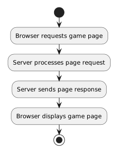
Imagine a simple web interaction where the browser requests a page that presents information about a Parcheesi game.

The purpose of the diagram is not to design a full online game.

It is to show the web interaction.

For example:
Plain text
Browser requests game page
        ↓
Server processes page request
        ↓
Server sends page response
        ↓
Browser displays game page

Keep the scenario subordinate to the networking concept.

Do not add game logic that is unrelated to the request/response flow.

The Diagram Should Show Responsibility, Not Just Order

Without partitions, this sequence:

Plain text
Send request
Receive request
Send response
Receive response

shows order.

With partitions, the diagram also shows:

That responsibility information is the reason to use swimlanes.

Do Not Put Server Work in the Browser Lane

A common modeling mistake is to place every action in the same lane because the user experiences everything through the browser.

Remember:

The browser displays the result.

The server processes the server-side request.

The user seeing the result in the browser does not mean the browser performed every step.

Do Not Treat the Network as a Magic Action

You may be tempted to add a single box:

Plain text
Internet happens

That does not explain the interaction.

The current model does not need detailed routers or network layers, but it should still show the meaningful transfer:

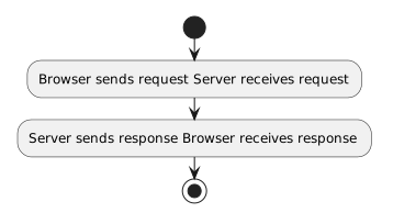
Plain text
Browser sends request → Server receives request
Server sends response → Browser receives response

The Internet provides the connectivity between those endpoints.

Keep the Scope Introductory

Do not add concepts that have not yet been introduced, such as:

Those may be important in other courses.

They are not needed to model the basic web request.

Read the Final Diagram as a Story

A strong diagram should let you say:

The browser interprets the URL, creates a request, and sends it to the server. The server receives and processes the request, creates a response, and sends it back. The browser receives the response, interprets it, and displays the result.

If the UML communicates that story clearly, the model is doing its job.