Boolean Values Represent True/False State
A Boolean value is either:
- true
- false
A name such as:
isAvailable
gives the value meaning.
Read:
- New
- Changed
- Removed
A computer program works from instructions that have been represented in the software.
People often fill in missing information automatically.
Programs cannot safely rely on unstated assumptions.
Clear technical instructions identify:
An instruction is ambiguous when it allows more than one reasonable interpretation.
For example:
raises questions such as:
A more precise requirement defines the intended meaning.
Precision does not mean adding unnecessary detail.
It means removing uncertainty that affects the required behavior.
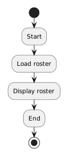
In a simple sequence, statements execute in order.
For example:
Player player1 = new Player();
player1.name = "Jordan";
player1.isAvailable = true;
The Player object is created before its fields are assigned.
Later statements operate on the state produced by earlier statements.
Changing the order can change the result or make a later instruction impossible to perform.
A Boolean value is either:
A name such as:
isAvailable
gives the value meaning.
Read:
A decision node allows one incoming flow to continue along different outgoing paths.
For example:
![Activity diagram showing Is the player available?, then [yes] Add player to available list, then [no] Continue without adding.](Diagrams/0.3.QuizStudyGuide.Activity.DecisionNodesRepresentChoices.light.svg)
The condition determines which path applies.
A useful decision diagram makes the meaning of each path clear.
A UML object diagram focuses on a snapshot:
A UML activity diagram focuses on behavior:
A useful shortcut is:
Object diagram: What exists right now?
Activity diagram: What happens next?
Violet is the diagramming tool used to create activity diagrams.
The tool can place nodes and connectors.
It does not decide whether the modeled process is correct.
The reasoning should be clear before or while the UML is constructed:
process meaning → UML flow
An editable Violet file is the source artifact that can be reopened and revised.
Visual Studio organizes the development workspace as:
Solution → Project → Files
Solution Explorer helps you navigate that structure.
Common file types include:
Use the supplied solution structure rather than reorganizing files before you understand their roles.
A breakpoint tells Visual Studio to pause when execution reaches a selected location.
Choose a breakpoint based on a question.
For example:
The breakpoint creates a moment where you can inspect the runtime state.
It does not fix the program.
When the program is paused, F10 / Step Over executes the current statement and advances to the next point in the current flow.
A useful debugging rhythm is:
Predict → Step → Observe → Compare
F10 helps connect the written sequence of source statements to the state changes that occur at runtime.
The Visual Studio Error List organizes compiler and build feedback.
A build error can prevent the current source from being compiled successfully.
Use the Error List to locate and read the reported problem, then inspect the surrounding source.
A successful build does not prove that the program meets the requirement.
Code can compile successfully and still contain the wrong value or logic.
An activity diagram might show:
![Activity diagram showing Read availability, then Decision: available?, then [yes] Display available result, then [no] Continue.](Diagrams/0.3.QuizStudyGuide.Activity.UMLFlowCanBe.light.svg)
The C# source must preserve the same intended flow when it implements that behavior.
The diagram and the source are different representations.
The important question is whether they describe the same actions and paths.
Example:
if (player1.isAvailable)
{
    System.Console.WriteLine("Player is available.");
}
If the condition is true, the block runs.
If the condition is false, the block is skipped.
Execution then continues after the if.
Example:
if (player1.isAvailable)
{
    System.Console.WriteLine("Available");
}
else
{
    System.Console.WriteLine("Unavailable");
}
If the condition is true, the if block runs.
If the condition is false, the else block runs.
Exactly one of the two branches is selected for that evaluation.
Module 3 brings several representations and tools together:
Requirement
Defines what the process should accomplish.
Activity diagram
Shows the intended actions and paths visually.
C# source
Contains executable instructions.
Boolean state
Provides true/false information used by a decision.
Breakpoint
Creates a planned pause.
F10
Lets you trace the flow statement by statement.
Debugger state
Shows the values that actually exist during execution.
Error List
Reports compiler/build diagnostics.
Strong program analysis comes from knowing which source answers which question.
The main progression is:
Clear instructions → Sequence → Boolean state → Visual decision flow → C# decision → Runtime observation
Each step adds another way to reason about what the program should do and what it actually does.