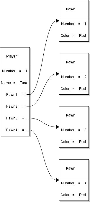
In 0.2 Parcheesi, you created one Player object and four Pawn objects. In 0.3, you used an activity diagram to describe a move. In this assessment, you will create a class diagram that describes the information each kind of object can contain. Build Player first, connect it to Pawn, and then add Game to complete the model.
Keep working in the same Violet class diagram throughout this assignment. Your final submission will contain the Game, Player, and Pawn classes and their relationships.
Your completed 0.2 object diagram shows one particular player: Tara, whose Number is 1. The class diagram describes the fields that every Player object can have. It does not select a particular player or assign Tara's values.
In the object diagram, Number = 1 and Name = Tara are values belonging to one Player object. In the class diagram, you will write Number : int and Name : string to describe the kinds of information Player objects can hold. Different Player objects can use the same field definitions while holding different values.
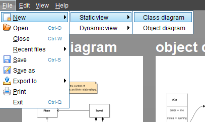
Open a blank class diagram in Violet. You will build the model one small piece at a time.
Open Violet UML Diagramming Tool and create a new Class diagram. Find the diagram toolbar shown below. You will use its class tool to add boxes and its association tool to connect them.
Leave room to the right for Pawn and above and to the left for Game.
Start with just one class box. You will name it in the next step and add its fields after that.
Click the class tool shown in the screenshot, then click once in the workspace to place a class box.
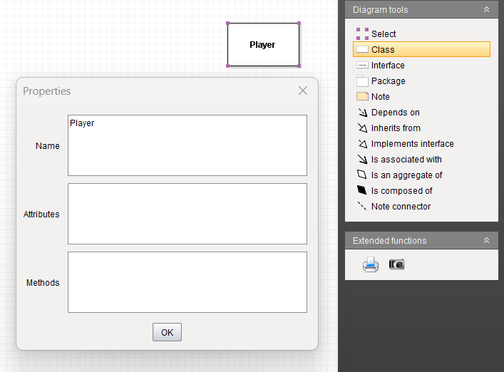
Leave the new class at its default name for now. Do not add any fields or methods. At this point, you are only placing the box that will hold your class information.
Name the empty class Player, then add its first field: Number : int. Leave the player's Name field for the next step.
Double-click the class to open its properties. Enter Player in the class name field and confirm the change. Leave the attributes and methods compartments empty.
The class name belongs at the top of the box. This is different from the Name : string field you will add later: Player names the kind of object, while Name will hold an individual player's name.
Open the Player class properties. You will add the field to the attributes compartment, which lists the information the class defines. Confirm the change after entering it.
Enter Number : int in the attributes compartment.
A field is a named place for information in an object. A field definition gives both its name and its type: the kind of value the field can hold. In a class diagram, write the field name first, a colon, and then the type. Read Number : int as “Number is a field of type int.” The colon separates the name from the type; it does not assign a value.
The type int is short for integer. It stores whole numbers, including values such as 0, 1, 2, and -1, without a fractional part. A value such as 1.5 does not fit this type. Number uses int because a player's identifying number is a whole number.
The type tells you what kind of data is possible; game rules can limit it further. For example, int can represent a negative number even if your game does not allow negative player numbers. Writing int alone does not enforce the game's rules or choose a starting value.
In 0.2, Number = 1 told you the number of one particular Player object. Here, Number : int tells you that Player objects have a whole-number field named Number. Enter the type, not the value 1.
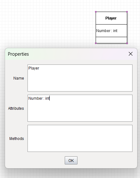
Your class should be labeled Player and contain only Number : int. Do not add Name : string yet.
Keep Number : int and add a second field for the player's name. Your Player class will then contain both a whole-number field and a text field.
Open the Player class properties. Keep Number : int and add Name : string on the next line in the attributes compartment.
A string is a sequence of characters used to represent text. A character can be a letter, a digit, a space, or punctuation. Tara is a string made from four characters: T, a, r, and a. A name such as Tara Smith contains a space, and Player 2 contains both letters and a digit. All of these can be stored as string values.
In written programming examples, double quotation marks identify a text value: "Tara", "Player 2", or "Red". The quotation marks mark the beginning and end of the text; they are not part of the name itself. A string can also contain no characters, written as "", which is called an empty string.
Digits inside a string are still text. The integer 12 represents a number that can be used in arithmetic. The string "12" represents the two characters 1 and 2. A field's type tells the program how to treat the value; it does not depend only on how the value looks.
For this diagram, enter Name : string. Do not enter Name : Tara or put quotation marks around string. Name is the field name, string is its type, and "Tara" is one possible value that a Player object could hold. Two Player objects could hold "Tara" and "Sam" in their Name fields while using the same Player class.
The Player class now defines two different kinds of information: Number holds a whole number, and Name holds text. Each Player object gets its own values for those fields.
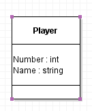
Check the fields in your Player class. It contains Number : int and Name : string, each on its own line. It does not contain the values 1 or Tara, and its methods compartment is empty.
Use the class tool to add a second class. Open its properties and name it Pawn. You need only one Pawn class box.
Enter these two fields on separate lines in Pawn's attributes compartment. Leave its methods compartment empty.
Add Number : int for the pawn's whole-number identifier. The four Pawn objects in 0.2 held the values 1, 2, 3, and 4 in this field.
Add Color : string for the color's name as text. In 0.2, that value was Red. Here, string tells you the field holds text; it does not limit the field to a predefined set of color names or draw the pawn in that color. Those behaviors would require additional rules or code later.
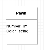
Confirm that Pawn has Number : int and Color : string on separate lines. Keep Player's existing fields. You will connect the two classes in the next step.
Review your completed object diagram from 0.2. Each Pawn object has its own Number and Color values. They share the same field structure, so one Pawn class can describe them all.
The object diagram links Tara's Player object to particular Pawn objects. The class diagram will describe the reference fields through which a Player object can refer to Pawn objects. It does not identify which particular objects exist in a running game.
Review the comparison with the 0.2 object diagramUse Violet's association connection tool to draw a line from Player to Pawn. The arrowhead must point toward Pawn. Use an association, not an inheritance connection with a hollow triangle.
Open the connection properties. Set the middle label to Pawn1 and the end label at the Pawn end to 1. Leave the start label blank.
Pawn1 is the field name; Pawn is the type of object it references. A field's type can be a class you define, as well as a built-in type such as int or string. Number holds an integer value, Name holds text, and Pawn1 holds a reference to a Pawn object. That reference lets a Player refer to a separate object that has its own Number and Color fields. The arrow points from the class holding the reference toward the referenced class. The 1 at the Pawn end means that this reference is associated with one Pawn in this model. It is not the Number value of that pawn.
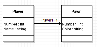
Check that Pawn1 points from Player to Pawn and has 1 at the Pawn end. Follow the arrow and explain it as: “A Player has a field named Pawn1 that refers to one Pawn object.” The line describes a relationship; it does not show a pawn moving or an action happening.
Draw three more directed associations from Player to Pawn. Give each line its own middle label and put 1 at its Pawn end.
Keep Pawn1 and name the three new associations Pawn2, Pawn3, and Pawn4. All four arrows point toward Pawn, and each has an end label of 1.
Keep the lines separated so every label and arrowhead is readable. Do not add three more Pawn class boxes or replace these four lines with one line labeled 4.
| In the 0.2 object diagram | In this class diagram |
|---|---|
| Four separate Pawn boxes show four objects | One Pawn box defines their shared structure |
| Each Pawn has its own Number and Color values | Pawn defines Number : int and Color : string |
| Player's Pawn1 through Pawn4 link to particular objects | Player's Pawn1 through Pawn4 each refer to the Pawn type |
| You can see which object each field references | You can see that several fields can share the same object type |
The four class-diagram arrows all reach Pawn because the four fields have the same type. This does not mean all four fields must refer to the same object. In the 0.2 example, they refer to four distinct Pawn objects.
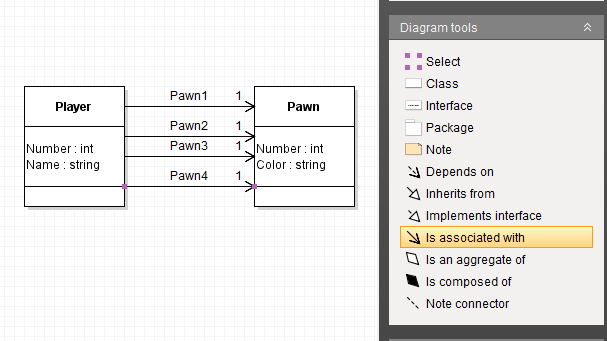
Confirm that there are two class boxes and four associations, with the field names and types entered above. Explain why one class can have several different object-reference fields whose type is Pawn.
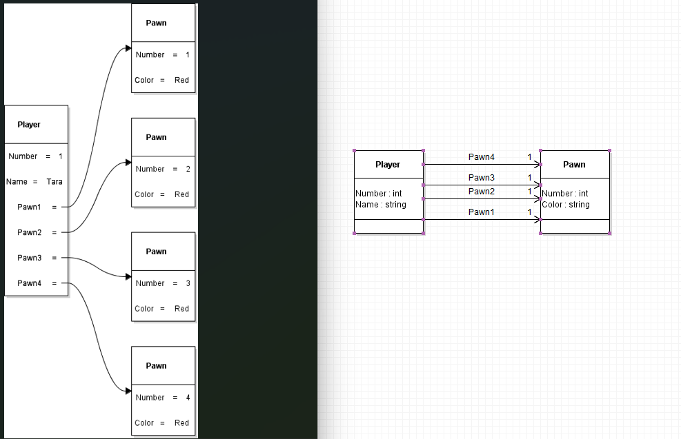
On the left is the object diagram from the beginning of this assignment. It shows one particular Player, Tara, connected to four separate Pawn objects. Each pawn has its own Number value and a Color value of Red.
On the right is the Player class with four Pawn references that you completed earlier. It shows one Player class and one Pawn class. The boxes describe the field names and types shared by objects of those classes, rather than the values of particular objects.
Follow Pawn1 in each view. On the left, it reaches one particular Pawn object. On the right, it reaches the Pawn class to show the type of object that the field references. Pawn2, Pawn3, and Pawn4 work the same way. Four arrows pointing to one class do not mean there is only one Pawn object in the game.
Both diagrams describe the four named references. The object diagram shows the particular objects connected by those references; the class diagram defines the structure those objects use.
Place a Game class above and to the left of Player. Enter the following fields on separate lines in its attributes compartment, in the order shown. Leave the methods compartment empty.
- WinningsPot : decimal
- PlayerCount : int
- Name : string
WinningsPot : decimal describes an amount of money. The decimal type can represent numbers with a fractional part, such as 12.50 or 3.75. It is suitable for decimal amounts such as money, where the digits after the decimal point matter. An int would not represent the fractional part of 12.50. The type does not supply a currency symbol or format the amount for display; those are separate choices.
PlayerCount : int describes how many players are in the game. This is a whole-number count: a game could have 2 or 4 players, but not 2.5 players.
Name : string describes the game's name as text, such as "Friday Game". As with Player.Name, enter the field definition in the diagram, not that example value.
These fields belong to Game because they describe the game as a whole. Game.Name and Player.Name are separate fields in different classes: one describes a game, and the other describes a player.
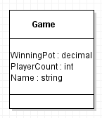
Check that your Game class has these three fields. Leave it unconnected while you compare the two views of Player and Pawn below.
Finish the model by connecting Game to the Player class you have already built. Keep all four existing Player-to-Pawn associations.
Draw a directed association from Game to Player, with its arrowhead pointing toward Player. In the connection properties, set the middle label to Players and the end label at Player to *. Leave the start label blank.
The * is a multiplicity label meaning zero or more, often read as “many.” It shows that the Players relationship can include multiple Player objects. The single Player class box describes their shared structure; it is not a count of the players in a particular game.
PlayerCount records a number. The Players relationship describes access to Player objects. They represent different kinds of information. You are modeling that relationship here, not implementing a collection or writing code to keep the count updated.
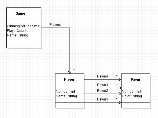
Your Game class is now connected to the rest of the model, and the diagram is complete. Compare it with the completed model above, then use the checklist below to verify your work. This is the diagram you will save and submit.
- There are exactly three classes: Game, Player, and Pawn.
- Game has WinningsPot : decimal, PlayerCount : int, and Name : string.
- Player has Number : int and Name : string.
- Pawn has Number : int and Color : string.
- The Players association points from Game to Player and shows * at the Player end.
- Four separate associations named Pawn1, Pawn2, Pawn3, and Pawn4 point from Player to Pawn, each with 1 at the Pawn end.
- The classes contain field definitions and types, not particular object values.
- All methods compartments remain empty, and every label is readable.
Save your completed Game–Player–Pawn class diagram and use the Feedback System to check it. Submit your editable Violet diagram file, not a screenshot.
Choose File > Save. Use the base filename Parcheesi 0.4 LastName, replacing LastName with your last name. Confirm that the saved filename ends with .class.violet.html.
ZIP the .class.violet.html file itself without first placing it inside another folder. Use the ZIP filename Parcheesi 0.4 LastName.class.violet.html.zip and submit it to the Feedback System for this assignment.
Read the returned feedback. Correct any reported issues in Violet, save the corrected file, ZIP it again, and resubmit it. Repeat until the required feedback is resolved.
Submit the resulting Feedback System URL to Canvas as directed by your course.