The purpose of this document is to walk you through configuring the route on your host computer to support accessing your GNS3 virtual network, shown in the image below, from PCA to R1 (Fa0/1).
Prerequisites:
You must have your basic, working, network template completed from LP1 - see NS-Pat-1-4-GNS3.html.
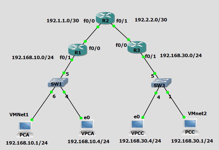
IP Address Table:
| Device | Interface | IP Address | Subnet Mask | Default Gateway | Switch Port |
|---|---|---|---|---|---|
| R1 | Fa0/1 | 192.168.10.254 | 255.255.255.0 | N/A | 5 |
| Fa0/0 | 192.1.1.1 | 255.255.255.252 | N/A | N/A |
|
| R2 | Fa0/0 | 192.1.1.2 | 255.255.255.252 | N/A | N/A |
| Fa0/1 | 192.2.2.2 | 255.255.255.252 | N/A | N/A | |
| R3 | Fa0/1 | 192.168.30.254 | 255.255.255.0 | N/A | 5 |
| Fa0/0 | 192.2.2.1 | 255.255.255.252 | N/A | N/A | |
| PCA | VM NIC | 192.168.10.1 | 255.255.255.0 | 192.168.10.254 | Any |
| VPCA | VPC Eth | 192.168.10.4 | 255.255.255.0 | 192.168.10.254 | Any |
| PCC | VM NIC | 192.168.30.1 | 255.255.255.0 | 192.168.30.254 | Any |
| VPCC | VPC Eth | 192.168.30.4 | 255.255.255.0 | 192.168.30.254 | Any |
When you are performing your network security labs using a simulated GNS3 network, you will be asked on numerous occasions in the lab to access your R1 router from the internal network represented by PCA. Before you do this you should configure the routing table on your host computer to support access to the virtual network via the virtual network interface represented by VMnet1 and that is assigned the IP address of 192.168.10.1. In this document we will assume that this network interface (VMnet1) was established using the within VMware Workstation; it can be identified by displaying the IP configuration of your host computer using ipconfig/all and looking for VMnet1 in the description of the interface.
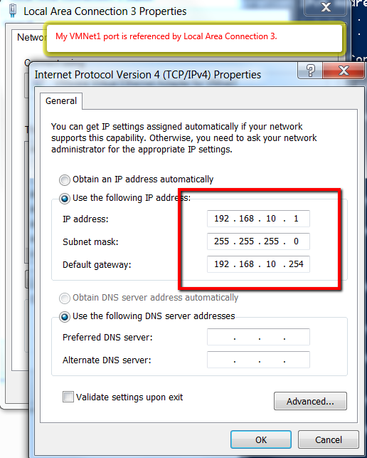
First, verify that your VMNet1 interface is correctly configured and then change the routing table on your host computer to force the route through the 192.168.10.1 interface (VMnet1).
- Verify that your VMNet1 interface is configured as shown in the image below:
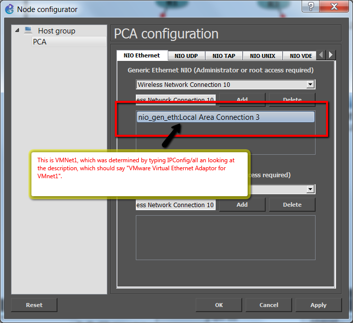
- Verify that your GNS3, PCA host is properly connected to the VMNet1 interface, see images below:
Change your routing table.
- Delete the static route to be sure that it does not exist in a different form (you may get an error indicating that the entry was not found, this is ok):
route delete 192.168.10.254
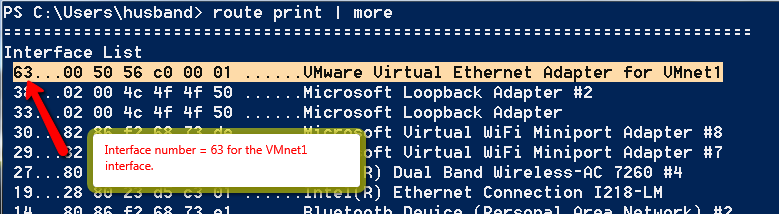
- Determine what the Interface number is for your VMnet1 interface:
route print | more
- Change the route:
route add 192.168.10.254 mask 255.255.255.255 192.168.10.254 metric 30 IF 63
The output of this command should just state that the command completed ("OK"). This command will add a route specific to the 192.168.10.254 address (hence the 255.255.255.255 mask). The first occurrence of this address is the destination address, the second occurrence of this address is the gateway address (the actual virtual router). The metric of 30 is low enough to override the default settings in the routing table. The interface that is selected for this route is based on the interface number specified (IF 63).
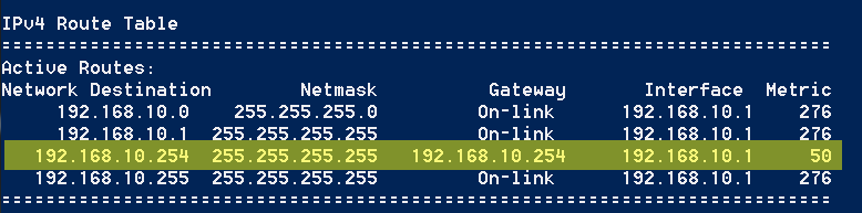
- Verify your routing table by printing a portion of the ipv4 table by typing the following command:
route print -4 *192.168.10*
This command prints the IPv4 routing table. The output that you are interested in will display at the bottom of the display. Look for your custom entry.
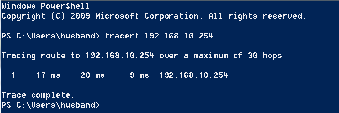
- Verify with the tracert command that your route is through the correct interface, the one that PCA is virtually connected to by typing the following command:
tracert 192.168.10.254
If this command shows that you are NOT taking a route through your virtual R1 router (the gateway), then check your routing table to make sure that your custom route is indeed the only route that exists that would satisfy the desired destination of 192.168.10.254.
You will now be routed through VMnet1 to get to your virtual network if your target address is 192.168.10.254.